Showing posts with label TECNOLOGY AND KNOWLEDGE. Show all posts
Showing posts with label TECNOLOGY AND KNOWLEDGE. Show all posts
Sunday, 26 June 2016
Friday, 3 June 2016

Wednesday, 28 October 2015
Saturday, 24 October 2015

Piston-type motors can be in-line-axis or bent-axis types.
(1) In-Line-Axis, Piston-Type Motors. These motors (Figure 4-15) are almost identical to the pumps. They are built-in, fixed- and variable-displacement models in several sizes. Torque is developed by a pressure drop through a motor. Pressure exerts a force on the ends of the pistons, which is translated into shaft rotation. Shaft rotation of most models can be reversed anytime by reversing the flow direction.

Oil from a pump is forced into the cylinder bores through a motor's inlet port. Force on the pistons at this point pushes them against a swash plate. They can move only by sliding along a swash plate to a point further away from a cylinder's barrel, which causes it to rotate. The barrel is then splined to a shaft so that it must turn.
A motor's displacement depends on the angle of a swash plate (Figure 4-16). At maximum angle, displacement is at its highest because the pistons travel at maximum length. When the angle is reduced, piston travel shortens, reducing displacement. If flow remains constant, a motor runs faster, but torque is decreased. Torque is greatest at maximum displacement because the component of piston force parallel to a swash plate is greatest.

(2) Bent-Axis, Piston-Type Motors. These motors are almost identical to the pumps. They are available in fixed- and variable-displacement models (Figure 4-17), in several sizes. Variable-displacement motors can be controlled mechanically or by pressure compensation. These motors operate similarly to in-line motors except that piston thrust is against a drive-shaft flange. A parallel component of thrust causes a flange to turn. Torque is maximum at maximum displacement; speed is at a minimum. This design piston motor is very heavy and bulky, particularly the variable-displacement motor. Using these motors on mobile equipment is limited.

Although some piston-type motors are controlled by directional-control valves, they are often used in combination with variable-displacement pumps. This pump-motor combination (hydraulic transmission) is used to provide a transfer of power between a driving element, such as an electric motor, and a driven element. Hydraulic transmissions may be used for applications such as a speed reducer, variable speed drive, constant speed or constant torque drive, and torque converter. Some advantages a hydraulic transmission has over a mechanical transmission is that it has-
• Quick, easy speed adjustment over a wide range while the power source is operating at constant (most efficient) speed.
• Rapid, smooth acceleration or deceleration.
• Control over maximum torque and power.
• A cushioning effect to reduce shock loads.
• A smooth reversal of motion.
Maintenance.
Hydraulic cylinders are compact and relatively simple. The key points to watch are the seals and pivots. The following lists service tips in maintaining cylinders:
a. External Leakage. If a cylinder's end caps are leaking, tighten them. If the leaks still do not stop, replace the gasket. If a cylinder leaks around a piston rod, replace the packing. Make sure that a seal lip faces toward the pressure oil. If a seal continues to leak, check paragraphs 4-3e through i.
b. Internal Leakage. Leakage past the piston seals inside a cylinder can cause sluggish movement or settling under load. Piston leakage can be caused by worn piston seals or rings or scored cylinder walls. The latter may be caused by dirt and grit in the oil. NOTE: When repairing a cylinder, replace all the seals and packings before reassembly.
c. Creeping Cylinder. If a cylinder creeps when stopped in midstroke, check for internal leakage (paragraph 4-3b). Another cause could be a worn control valve.
d. Sluggish Operation. Air in a cylinder is the most common cause of sluggish action. Internal leakage in a cylinder is another cause. If an action is sluggish when starting up a system, but speeds up when a system is warm, check for oil of too high a viscosity (see the machine's operating manual). If a cylinder is still sluggish after these checks, test the whole circuit for worn components.
e. Loose Mounting. Pivot points and mounts may be loose. The bolts or pins may need to be tightened, or they may be worn out. Too much slop or float in a cylinder's mountings damages the piston-rod seals. Periodically check all the cylinders for loose mountings.
f. Misalignment. Piston rods must work in-line at all times. If they are side-loaded, the piston rods will be galled and the packings will be damaged, causing leaks. Eventually, the piston rods may be bent or the welds broken.
g. Lack of Lubrication. If a piston rod has no lubrication, a rod packing could seize, which would result in an erratic stroke, especially on single-acting cylinders.
h. Abrasives on a Piston Rod. When a piston rod extends, it can pick up dirt and other material. When it retracts, it carries the grit into a cylinder, damaging a rod seal. For this reason, rod wipers are often used at the rod end of a cylinder to clean the rod as it retracts. Rubber boots are also used over the end of a cylinder in some cases. Piston rods rusting is another problem. When storing cylinders, always retract the piston rods to protect them. If you cannot retract them, coat them with grease.
i. Burrs on a Piston Rod. Exposed piston rods can be damaged by impact with hard objects. If a smooth surface of a rod is marred, a rod seal may be damaged. Clean the burrs on a rod immediately, using crocus cloth. Some rods are chrome-plated to resist wear. Replace the seals after restoring a rod surface.
j. Air Vents. Single-acting cylinders (except ram types) must have an air vent in the dry side of a cylinder. To prevent dirt from getting in, use different filter devices. Most are self-cleaning, but inspect them periodically to ensure that they operate properly.
Construction and Application.
A cylinder is constructed of a barrel or tube, a piston and rod (or ram), two end caps, and suitable oil seals. A barrel is usually seamless steel tubing, or cast, and the interior is finished very true and smoothly. A steel piston rod is highly polished and usually hard chrome-plated to resist pitting and scoring. It is supported in the end cap by a bushing or polished surface.
The cylinder's ports are built into the end caps, which can be screwed on to the tubes, welded, or attached by tie bolts or bolted flanges. If the cylinder barrel is cast, the head-end cap may be integral with it. Mounting provisions often are made in the end caps, including flanges for stationary mounting or clevises for swinging mounts.
Seals and wipers are installed in the rod's end cap to keep the rod clean and to prevent external leakage around the rod. Other points where seals are used are at the end cap and joints and between the piston and barrel. Depending on how the rod is attached to the piston, a seal may be needed. Internal leakage should not occur past a piston. It wastes energy and can stop a load by a hydrostatic lock (oil trapped behind a piston).
Figure 4-8 shows force-and-motion applications of cylinders. Because fluid power systems have many requirements, actuating cylinders are available in different shapes and sizes. A cylinder-type actuator is versatile and may be the most trouble-free component of fluid-powered systems. A cylinder and a mechanical member of a unit to be actuated must be aligned correctly. Any misalignment will cause excessive wear of a piston, a piston rod, and the seals. Also, a piston rod and an actuating unit must stay properly adjusted. Clean the exposed ends of the piston rods to ensure that foreign matter does not get into the cylinders.

Friday, 23 October 2015
The hydraulic supply and return line is connected to the lower chamber and allows hydraulic fluid to flow to and from the lower chamber of the actuator. The stem transmits the motion of the piston to a valve.

Figure 37 Hydraulic Actuator
Initially, with no hydraulic fluid pressure, the spring force holds the valve in the closed position. As fluid enters the lower chamber, pressure in the chamber increases. This pressure results in a force on the bottom of the piston opposite to the force caused by the spring. When the hydraulic force is greater than the spring force, the piston begins to move upward, the spring compresses, and the valve begins to open. As the hydraulic pressure increases, the valve continues to open. Conversely, as hydraulic oil is drained from the cylinder, the hydraulic force becomes less than the spring force, the piston moves downward, and the valve closes. By regulating amount of oil supplied or drained from the actuator, the valve can be positioned between fully open and fully closed.
Most piston-type cylinders are double-acting, which means that fluid under pressure can be applied to either side of a piston to provide movement and apply force in a corresponding direction. Figure 4-6 shows a double-acting piston-type cylinder. This cylinder contains one piston and piston-rod assembly and operates from fluid flow in either direction. The two fluid ports, one near each end of a cylinder, alternate as an inlet and an outlet, depending on the directional-control valve flow direction. This is an unbalanced cylinder, which means that there is a difference in the effective working area on the two sides of a piston. A cylinder is normally installed so that the head end of a piston carries the greater load; that is, a cylinder carries the greater load during a piston-rod extension stroke.
Figure 4-6 shows a balanced, double-acting, piston-type cylinder. The effective working area on both sides of a piston is the same, and it exerts the same force in both directions.

g. Cushioned Cylinder. To slow an action and prevent shock at the end of a piston stroke, some actuating cylinders are constructed with a cushioning device at either or both ends of a cylinder. This cushion is usually a metering device built into a cylinder to restrict the flow at an outlet port, thereby slowing down the motion of a piston. Figure 4-7 shows a cushioned actuating cylinder.

h. Lockout Cylinders. A lockout cylinder is used to lock a suspension mechanism of a tracked vehicle when a vehicle functions as a stable platform. A cylinder also serves as a shock absorber when a vehicle is moving. Each lockout cylinder is connected to a road arm by a control lever. When each road wheel moves up, a control lever forces the respective cylinder to compress. Hydraulic fluid is forced around a piston head through restrictor ports causing a cylinder to act as a shock absorber. When hydraulic pressure is applied to an inlet port on each cylinder's connecting eye, an inner control-valve piston is forced against a spring in each cylinder. This action closes the restrictor ports, blocks the main piston's motion in each cylinder, and locks the suspension system.
Rotary Actuators- Hydraulic Motors.
Hydraulic motors convert hydraulic energy into mechanical energy. In industrial hydraulic circuits, pumps and motors are normally combined with a proper valving and piping to form a hydraulic-powered transmission. A pump, which is mechanically linked to a prime mover, draws fluid from a reservoir and forces it to a motor. A motor, which is mechanically linked to the workload, is actuated by this flow so that motion or torque, or both, are conveyed to the work. Figure 4-9 shows the basic operations of a hydraulic motor.

The principal ratings of a motor are torque, pressure, and displacement. Torque and pressure ratings indicate how much load a motor can handle. Displacement indicates how much flow is required for a specified drive speed and is expressed in cubic inches per revolutions, the same as pump displacement. Displacement is the amount of oil that must be pumped into a motor to turn it one revolution. Most motors are fixed-displacement; however, variable-displacement piston motors are in use, mainly in hydrostatic drives. The main types of motors are gear, vane, and piston. They can be unidirectional or reversible. (Most motors designed for mobile equipment are reversible.)
a. Gear-Type Motors. Figure 4-10 shows a gear-type motor. Both gears are driven gears, but only one is connected to the output shaft. Operation is essentially the reverse of that of a gear pump. Flow from the pump enters chamber A and flows in either direction around the inside surface of the casing, forcing the gears to rotate as indicated. This rotary motion is then available for work at the output shaft.

b. Vane-Type Motors. Figure 4-11 shows a vane-type motor. Flow from the pump enters the inlet, forces the rotor and vanes to rotate, and passes out through the outlet. Motor rotation causes the output shaft to rotate. Since no centrifugal force exists until the motor begins to rotate, something, usually springs, must be used to initially hold the vanes against the casing contour. However, springs usually are not necessary in vane-type pumps because a drive shaft initially supplies centrifugal force to ensure vane-to-casing contact.

Vane motors are balanced hydraulically to prevent a rotor from side-loading a shaft. A shaft is supported by two ball bearings. Torque is developed by a pressure difference as oil from a pump is forced through a motor. Figure 4-12 shows pressure differential on a single vane as it passes the inlet port. On the trailing side open to the inlet port, the vane is subject to full system pressure. The chamber leading the vane is subject to the much lower outlet pressure. The difference in pressure exerts the force on the vane that is, in effect, tangential to the rotor. This pressure difference is effective across vanes 3 and 9 as shown in Figure 4-13. The other vanes are subject to essentially equal force on both sides. Each will develop torque as the rotor turns. Figure 4-13 shows the flow condition for counterclockwise rotation as viewed from the cover end. The body port is the inlet, and the cover port is the outlet. Reverse the flow, and the rotation becomes clockwise.


In a vane-type pump, the vanes are pushed out against a cam ring by centrifugal force when a pump is started up. A design motor uses steel-wire rocker arms (Figure 4-14) to push the vanes against the cam ring. The arms pivot on pins attached to the rotor. The ends of each arm support two vanes that are 90 degrees apart. When the cam ring pushes vane A into its slot, vane B slides out. The reverse also happens. A motor's pressure plate functions the same as a pump's. It seals the side of a rotor and ring against internal leakage, and it feeds system pressure under the vanes to hold them out against a ring. This is a simple operation in a pump because a pressure plate is right by a high-pressure port in the cover.

Figure 37 Hydraulic Actuator
Initially, with no hydraulic fluid pressure, the spring force holds the valve in the closed position. As fluid enters the lower chamber, pressure in the chamber increases. This pressure results in a force on the bottom of the piston opposite to the force caused by the spring. When the hydraulic force is greater than the spring force, the piston begins to move upward, the spring compresses, and the valve begins to open. As the hydraulic pressure increases, the valve continues to open. Conversely, as hydraulic oil is drained from the cylinder, the hydraulic force becomes less than the spring force, the piston moves downward, and the valve closes. By regulating amount of oil supplied or drained from the actuator, the valve can be positioned between fully open and fully closed.
Most piston-type cylinders are double-acting, which means that fluid under pressure can be applied to either side of a piston to provide movement and apply force in a corresponding direction. Figure 4-6 shows a double-acting piston-type cylinder. This cylinder contains one piston and piston-rod assembly and operates from fluid flow in either direction. The two fluid ports, one near each end of a cylinder, alternate as an inlet and an outlet, depending on the directional-control valve flow direction. This is an unbalanced cylinder, which means that there is a difference in the effective working area on the two sides of a piston. A cylinder is normally installed so that the head end of a piston carries the greater load; that is, a cylinder carries the greater load during a piston-rod extension stroke.
Figure 4-6 shows a balanced, double-acting, piston-type cylinder. The effective working area on both sides of a piston is the same, and it exerts the same force in both directions.
g. Cushioned Cylinder. To slow an action and prevent shock at the end of a piston stroke, some actuating cylinders are constructed with a cushioning device at either or both ends of a cylinder. This cushion is usually a metering device built into a cylinder to restrict the flow at an outlet port, thereby slowing down the motion of a piston. Figure 4-7 shows a cushioned actuating cylinder.
h. Lockout Cylinders. A lockout cylinder is used to lock a suspension mechanism of a tracked vehicle when a vehicle functions as a stable platform. A cylinder also serves as a shock absorber when a vehicle is moving. Each lockout cylinder is connected to a road arm by a control lever. When each road wheel moves up, a control lever forces the respective cylinder to compress. Hydraulic fluid is forced around a piston head through restrictor ports causing a cylinder to act as a shock absorber. When hydraulic pressure is applied to an inlet port on each cylinder's connecting eye, an inner control-valve piston is forced against a spring in each cylinder. This action closes the restrictor ports, blocks the main piston's motion in each cylinder, and locks the suspension system.
Rotary Actuators- Hydraulic Motors.

The principal ratings of a motor are torque, pressure, and displacement. Torque and pressure ratings indicate how much load a motor can handle. Displacement indicates how much flow is required for a specified drive speed and is expressed in cubic inches per revolutions, the same as pump displacement. Displacement is the amount of oil that must be pumped into a motor to turn it one revolution. Most motors are fixed-displacement; however, variable-displacement piston motors are in use, mainly in hydrostatic drives. The main types of motors are gear, vane, and piston. They can be unidirectional or reversible. (Most motors designed for mobile equipment are reversible.)
a. Gear-Type Motors. Figure 4-10 shows a gear-type motor. Both gears are driven gears, but only one is connected to the output shaft. Operation is essentially the reverse of that of a gear pump. Flow from the pump enters chamber A and flows in either direction around the inside surface of the casing, forcing the gears to rotate as indicated. This rotary motion is then available for work at the output shaft.

b. Vane-Type Motors. Figure 4-11 shows a vane-type motor. Flow from the pump enters the inlet, forces the rotor and vanes to rotate, and passes out through the outlet. Motor rotation causes the output shaft to rotate. Since no centrifugal force exists until the motor begins to rotate, something, usually springs, must be used to initially hold the vanes against the casing contour. However, springs usually are not necessary in vane-type pumps because a drive shaft initially supplies centrifugal force to ensure vane-to-casing contact.

Vane motors are balanced hydraulically to prevent a rotor from side-loading a shaft. A shaft is supported by two ball bearings. Torque is developed by a pressure difference as oil from a pump is forced through a motor. Figure 4-12 shows pressure differential on a single vane as it passes the inlet port. On the trailing side open to the inlet port, the vane is subject to full system pressure. The chamber leading the vane is subject to the much lower outlet pressure. The difference in pressure exerts the force on the vane that is, in effect, tangential to the rotor. This pressure difference is effective across vanes 3 and 9 as shown in Figure 4-13. The other vanes are subject to essentially equal force on both sides. Each will develop torque as the rotor turns. Figure 4-13 shows the flow condition for counterclockwise rotation as viewed from the cover end. The body port is the inlet, and the cover port is the outlet. Reverse the flow, and the rotation becomes clockwise.


In a vane-type pump, the vanes are pushed out against a cam ring by centrifugal force when a pump is started up. A design motor uses steel-wire rocker arms (Figure 4-14) to push the vanes against the cam ring. The arms pivot on pins attached to the rotor. The ends of each arm support two vanes that are 90 degrees apart. When the cam ring pushes vane A into its slot, vane B slides out. The reverse also happens. A motor's pressure plate functions the same as a pump's. It seals the side of a rotor and ring against internal leakage, and it feeds system pressure under the vanes to hold them out against a ring. This is a simple operation in a pump because a pressure plate is right by a high-pressure port in the cover.
INTRODUCTION
A
hydraulic actuator receives pressure energy and converts it to mechanical force
and motion. An actuator can be linear or rotary. A linear actuator gives force
and motion outputs in a straight line. It is more commonly called a cylinder
but is also referred to as a ram, reciprocating motor, or linear motor. A
rotary actuator produces torque and rotating motion. It is more commonly called
a hydraulic motor or motor.


Hydraulic
Cylinder : This converts the energy of
pressure into straight line motion.


Hydraulic
Motor : This converts the energy of
pressure into rotational motion.
Linear actuators- Hydraulic cylinders.
A
cylinder is a hydraulic actuator that is constructed of a piston or plunger
that operates in a cylindrical housing by the action of liquid under pressure.
Figure 4-1 shows the basic parts of a cylinder. A cylinder housing is a tube in
which a plunger (piston) operates. In a ram-type cylinder, a ram actuates a
load directly. In a piston cylinder, a piston rod is connected to a piston to
actuate a load. An end of a cylinder from which a rod or plunger protrudes is a
rod end. The opposite end is a head end. The hydraulic connections are a
head-end port and a rod-end port (fluid supply).


a. Single-Acting Cylinder. This cylinder
(Figure 4-1) only has a head-end port and is operated hydraulically in one
direction. When oil is pumped into a port, it pushes on a plunger, thus
extending it. To return or retract a cylinder, oil must be released to a
reservoir. A plunger returns either because of the weight of a load or from
some mechanical force such as a spring. In mobile equipment, flow to and from a
single-acting cylinder is controlled by a reversing directional valve of a
single-acting type.
The
single-acting ram-type actuating cylinder is often used in the hydraulic jack.
The elevators used to move aircraft to and from the flight deck and hangar deck
on aircraft carriers also use cylinders of this type. In these elevators, the
cylinders are installed horizontally and operate the elevator through a series
of cables and sheaves. Fluid pressure forces the ram outward and lifts the
elevator. When fluid pressure is released from the ram, the weight of the
elevator forces the ram back into the cylinder. This, in turn, forces the fluid
back into the reservoir.
b.
Double-Acting Cylinder. This cylinder (Figure 4-2) must have ports at the head
and rod ends. Pumping oil into the head end moves a piston to extend a rod
while any oil in the rod end is pushed out and returned to a reservoir. To
retract a rod, flow is reversed. Oil from a pump goes into a rod end, and a
head-end port is connected to allow return flow. The flow direction to and from
a double-acting cylinder can be controlled by a double-acting directional valve
or by actuating a control of a reversible pump.


A
double-acting ram-type cylinder is illustrated in figure. In this cylinder,
both strokes of the ram are produced by pressurized fluid. There are two fluid
ports, one at or near each end of the cylinder. Fluid under pressure is
directed to the closed end of the cylinder to extend the ram and apply force.
A
four-way directional control valve is normally used to control the
double-acting ram. When the valve is positioned to extend the ram, pressurized
fluid enters port A (fig. 10-2), acts on the bottom surface of the ram, and
forces the ram outward. Fluid above the ram lip is free to flow out of port B,
through the control valve, and to the return line in hydraulic systems or to
the atmosphere in pneumatic systems.
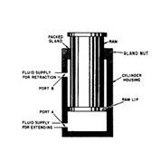

Figure
10-2.—Double-acting ram-type actuating cylinder.
Normally,
the pressure of the fluid is the same for either stroke of the ram. Recall that
force is equal to pressure times area (F= PA). Notice the difference of the
areas upon which the pressure acts in figure 10-2. The pressure acts against
the large surface area on the bottom of the ram during the extension stroke,
during which time the ram applies force. Since the ram does not require a large
force during the retraction stroke, pressure acting on the small area on the
top surface of the ram lip provides the necessary force to retract the ram.
c.
Differential Cylinder. In a differential cylinder, the areas where pressure is
applied on a piston are not equal. On a head end, a full piston area is
available for applying pressure. At a rod end, only an annular area is
available for applying pressure. A rod's area is not a factor, and what space
it does take up reduces the volume of oil it will hold. Two general rules about
a differential cylinder are that-
• With an equal GPM delivery to either
end, a cylinder will move faster when retracting because of a reduced volume
capacity.
• With equal pressure at either end, a
cylinder can exert more force when extending because of the greater piston
area. In fact, if equal pressure is applied to both ports at the same time, a
cylinder will extend because of a higher resulting force on a head end.
d.
Nondifferential Cylinder. This cylinder (Figure 4-3) has a piston rod extending
from each end. It has equal thrust and speed either way, provided that pressure
and flow are unchanged. A nondifferential cylinder is rarely used on mobile
equipment.


e.
Ram-Type Cylinder. A ram-type cylinder is a cylinder in which a cross-sectional
area of a piston rod is more than one-half a cross-sectional area of a piston
head. In many cylinders of this type, the rod and piston heads have equal
areas. A ram-type actuating cylinder is used mainly for push functions rather
than pull.
Figure
4-1 shows a single-acting, ram-type cylinder. A single-acting ram applies force
in one direction. This cylinder is often used in a hydraulic jack. In a
double-acting, ram-type cylinder, both strokes of a ram are produced by
pressurized fluid. Figure 4-2 shows this cylinder.
Figure
4-4 shows a telescoping, ram-type, actuating cylinder, which can be a single-
or double-acting type. In this cylinder, a series of rams are nested in a
telescoping assembly. Except for the smallest ram, each ram is hollow and
serves as a cylinder housing for the next smaller ram. A ram assembly is
contained in a main cylinder housing, which also provides the fluid ports.
Although an assembly requires a small space with all of the rams retracted, a
telescoping action of an assembly provides a relatively long stroke when the
rams are extended.


A
series of rams is nested in the telescoping assembly. With the exception of the
smallest ram, each ram is hollow and serves as the cylinder housing for the
next smaller ram. Although the assembly requires a small space with all the
rams retracted, the telescoping action of the assembly provides a relatively
long stroke when the rams are extended.
An
excellent example of the application of this type of cylinder is in the dump
truck. It is used to lift the forward end of the truck bed and dump the load.
During the lifting operation, the greatest force is required for the initial
lifting of the load.


Figure
10-3.—Telescoping ram-type actuating cylinder.
As
the load is lifted and begins to dump, the required force becomes less and less
until the load is completely dumped. During the raise cycle, pressurized fluid
enters the cylinder through port A (fig. 10-3) and acts on the bottom surface
of all three rams. Ram 1 has a larger surface area and, therefore, provides the
greater force for the initial load, As ram 1 reaches the end of its stroke and
the required force is decreased, ram 2 moves, providing the smaller force
needed to continue raising the load. When ram 2 completes its stroke, a still
smaller force is required. Ram 3 then moves outward to finish raising and
dumping the load. Some telescoping ram-type cylinders are of the single-acting
type. Like the single-acting ram discussed previously, these telescoping
ram-type cylinders are retracted by gravity or mechanical force. Some hydraulic
jacks are equipped with telescoping rams. Such jacks are used to lift vehicles
with low clearances to the required height. Other types of telescoping
cylinders, like the one illustrated in figure 10-3, are of the double-acting
type. In this type, fluid pressure is used for both the extension and
retraction strokes. A four-way directional control valve is commonly used to
control the operation of the double-acting type. Note the small passages in the
walls of rams 1 and 2. They provide a path for fluid to flow to and from the
chambers above the lips of rams 2 and 3. During the extension stroke, return
fluid flows through these passages and out of the cylinder through port B. It
then flows through the directional control valve to the return line or
reservoir.
To
retract the rams, fluid under pressure is directed into the cylinder through
port B and acts against the top surface areas of all three ram lips. This
forces the rams to the retracted position. The displaced fluid from the
opposite side of the rams flows out of the cylinder through port A, through the
directional control valve to the return line or reservoir.
f.
Piston-Type Cylinder. In this cylinder, a cross-sectional area of a piston head
is referred to as a piston-type cylinder. A piston-type cylinder is used mainly
when the push and pull functions are needed.
A
single-acting, piston-type cylinder uses fluid pressure to apply force in one
direction. In some designs, the force of gravity moves a piston in the opposite
direction. However, most cylinders of this type apply force in both directions.
Fluid pressure provides force in one direction and spring tension provides
force in the opposite direction.
Figure
4-5 shows a single-acting, spring-loaded, piston-type cylinder. In this
cylinder, a spring is located on the rod side of a piston. In some
spring-loaded cylinders, a spring is located on a blank side, and a fluid port
is on a rod end of a cylinder.


Typical
piston-type hydraulic actuator is shown in Figure 37. It consists of a
cylinder, piston, spring, hydraulic supply and return line, and stem. The piston
slides vertically inside the cylinder and separates the cylinder into two
chambers. The upper chamber contains the spring and the lower chamber contains
hydraulic oil.
Thursday, 22 October 2015
Wednesday, 21 October 2015
Monday, 19 October 2015
Subscribe to:
Comments (Atom)